
- #Old arduino nano schematic how to
- #Old arduino nano schematic serial
- #Old arduino nano schematic download
- #Old arduino nano schematic free
None of these instructions will produce a change on the screen without a display.display() method. SetCursor(x0, y0) Top left corner of the character The font included with the library is 5 pixels wide and 7 pixels tall but prints into a 6x8 pixel space.ĭrawChar(x, y, char, color, bg, size) // bg = background colour, char = ASCII no
#Old arduino nano schematic serial
These are based on the system used for printing to the Serial monitor with print() and println(). Graphical methods – draw is outline, fill is solidĭrawFastVLine(x0, y0,l,c) Fast vertical line of length lĭrawFastHLine(x0, y0,l,c) Fast horizontal line of length lĭrawRoundRect(x0, y0, w, h, r, c) Rounded corners of radius rįillRoundRect(x0, y0, w, h, r, c) Rounded corners of radius rĭisplay.fillCircle(63, 32, 30, SSD1306_WHITE) // Centred, white circle of radius 30 pixels The colour is specified by c, SSD1306_WHITE or SSD1306_BLACK.

(x0, y0) and (x1, y1) would define the first two positions, while h is the height and w the width of an object. The pixel in the bottom right corner is (127, 63).Īll the primitives have parameters which should be unsigned 16-bit integers (uint16_t). The addressable dimensions of the SSD1306 screen are 128 pixels left to right (0, 1, 2, …, 127) and 64 pixels from top to bottom (0, 1, 2, …, 63). Increasing the y value moves down the screen. The origin (0, 0) is at the top left of the screen. Points are defined by their Cartesian co-ordinates, (x, y). Bitmapped shapes can be scrolled or moved about the screen and the whole screen can be rotated. Text and numeric values, may be placed anywhere on the screen in a variety of sizes. Many drawing and writing primitives are provided: single pixel plotting, lines, circles, triangles, rectangles (with square and rounded corners), and corresponding filled shapes.
#Old arduino nano schematic how to
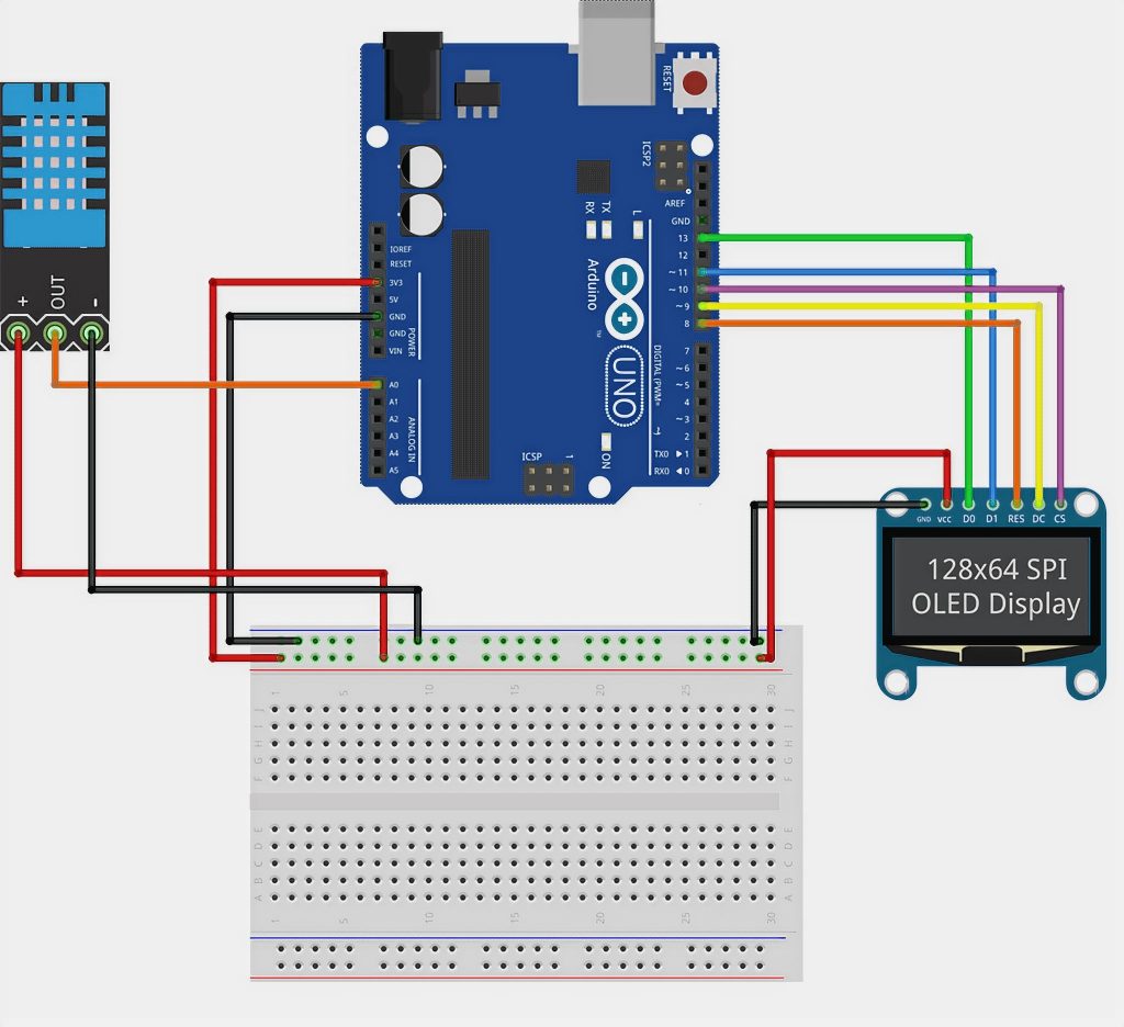
In this Instructable I am going to show you how to set it up and load the essential Libraries, explain the commands needed to program it and provide three example sketches: It can be powered directly from the Arduino with 5V and GND. It is an I2C device, and only uses two of the data pins, A4 and A5. It is widely available from a variety of outlets, including Adafruit, who provide many of the libraries we will be using. It is seen on the board here: The resistor array works like this: The resistor on this array is spare, so both terminals are grounded. I would not be without it and have bought several as they are cheap enough to leave embedded in projects. The resistor is one of 4 resistors that make up an SMD resistor array, RP2. This OLED (organic light-emitting diode) device is a very clear, inexpensive mono digital display and is a very useful addition to an Arduino user’s collection of parts. The SSD1306 may be small, only 0.96 inch on the diagonal, but it is much more useful and only SCL and SDA have to be connected. Most go for the simple version that ties up many of their digital I/O lines and buy a device which is built for text but cannot display a graph or geometrical shape. They are easily available, inexpensive and there are plenty of guides to help set them up. Many opt for a two-line 1602 LCD display.
#Old arduino nano schematic free
Unfortunately the old way of free downloads of the distribution with a request for donations resulted in something like a 0.01% donation rate and Fritzing was dying.Most Arduino owners soon decide that they would like to output text and results to a screen from their projects.
#Old arduino nano schematic download
One late issue I will point out, is that while Fritzing is open source and you are free to build it from source (which is quite difficult), in order to support the forum, websites and development, there is now a pay wall (which is causing a lot of concern) for the download of Fritzing. Making Fritzing parts is a fairly complex process (it took me a couple of years and a lot of help from here to learn to do it) so if you need changes or parts that don’t exist yet, feel free to ask. Or of course you could try to find an existing pcb design and use that. An Arduino board shouldn’t have too much components, so it shouldn’t be too hard (assuming you have some basic KiCad experience and PCB design knowledge). In this particular case I am the author of the part and you are free to use it for whatever you like. If you want to create the PCB design yourself, you can do that in the KiCad PCB editor (Pcbnew). In general all the parts are (I believe anyway) licensed under the Creative commons license.


 0 kommentar(er)
